

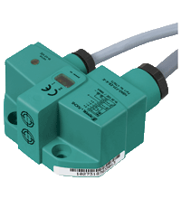
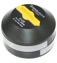
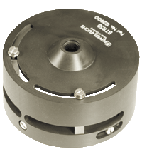
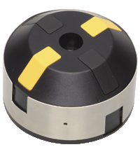
Inductive sensor NCN3-F31-N4-K-K
- Direct mounting on standard actuators
- Fixed setting
- Usable up to SIL 2 acc. to IEC 61508
- ATEX & IECEX certifications
NAMUR sensors must be operated with approved switch amplifiers. Please find suitable devices below:


Please note: All product-related documents, such as certificates, declarations of conformity, etc., which were issued prior to the conversion under the name Pepperl+Fuchs GmbH or Pepperl+Fuchs AG, also apply to Pepperl+Fuchs SE.
Výňatek z katalogového listu: Technická data NCN3-F31-N4-K-K
| General specifications | ||
|---|---|---|
| Switching function | 2 x normally closed (NC) | |
| Output type | NAMUR | |
| Rated operating distance | 3 mm | |
| Installation | flush mountable | |
| Assured operating distance | 0 ... 2.4 mm | |
| Actual operating distance | 2.7 ... 3.3 mm typ. | |
| Actuating element | Stainless steel 1.4305 / AISI 303 8.5 mm x 8.5 mm x 0.5 mm |
|
| Reduction factor rAl | 0.5 | |
| Reduction factor rCu | 0.4 | |
| Reduction factor r304 | 1 | |
| Reduction factor rSt37 | 1.3 | |
| Reduction factor rBrass | 0.6 | |
| Output type | 2-wire | |
| Nominal ratings | ||
| Nominal voltage | 8.2 V (Ri approx. 1 kΩ) | |
| Switching frequency | 0 ... 3 kHz | |
| Hysteresis | typ. 5 % | |
| Reverse polarity protection | reverse polarity protected | |
| Short-circuit protection | yes | |
| Suitable for 2:1 technology | yes , Reverse polarity protection diode not required | |
| Current consumption | ||
| Measuring plate not detected | ≥ 3 mA | |
| Measuring plate detected | ≤ 1 mA | |
| Time delay before availability | ≤ 1.1 ms | |
| Switching state indicator | LED, yellow | |
| Valve status indicator | LED, yellow | |
| Functional safety related parameters | ||
| Safety Integrity Level (SIL) | SIL 2 | |
| MTTFd | 1470 a | |
| Mission Time (TM) | 20 a | |
| Diagnostic Coverage (DC) | 0 % | |
| Valve circuit | ||
| Voltage | max. 32 V DC | |
| Current | max. 240 mA | |
| Short-circuit protection | no | |
| Reverse polarity protection | yes, with reversed output LED is out of function, therfore more power for solenoid valve | |
| Compliance with standards and directives | ||
| Standard conformity | ||
| NAMUR | EN 60947-5-6:2000 IEC 60947-5-6:1999 |
|
| Electromagnetic compatibility | NE 21:2007 | |
| Standards | EN 60947-5-2:2007 EN 60947-5-2/A1:2012 IEC 60947-5-2:2007 IEC 60947-5-2 AMD 1:2012 |
|
| Approvals and certificates | ||
| IECEx approval | ||
| Equipment protection level Ga | IECEx TUN 17.0021X | |
| Equipment protection level Gb | IECEx TUN 17.0021X | |
| Equipment protection level Da | IECEx TUN 17.0021X | |
| Equipment protection level Mb | IECEx TUN 17.0021X | |
| ATEX approval | ||
| Equipment protection level Ga | TÜV 99 ATEX 1479 X | |
| Equipment protection level Gb | TÜV 99 ATEX 1479 X | |
| Equipment protection level Da | TÜV 99 ATEX 1479 X | |
| UL approval | cULus Listed, General Purpose | |
| Ordinary Location | E87056 | |
| Hazardous Location | E501628 | |
| Control drawing | 116-0456 | |
| CCC approval | ||
| Hazardous Location | 2020322315002262 | |
| NEPSI approval | ||
| NEPSI certificate | GYJ19.1410X | |
| Ambient conditions | ||
| Ambient temperature | -25 ... 100 °C (-13 ... 212 °F) |
|
| Storage temperature | -40 ... 100 °C (-40 ... 212 °F) | |
| Mechanical specifications | ||
| Connection (system side) | PVC cable , 5 m | |
| Core cross section (system side) | 0.75 mm2 | |
| Connection (valve side) | PVC cable , 0.5 m | |
| Core cross section (valve side) | 0.75 mm2 | |
| Housing material | PBT | |
| Sensing face | PBT | |
| Degree of protection | IP67 | |
| Cable | ||
| Bending radius | > 10 x cable diameter | |
| Tightening torque, fastening screws | 4 Nm ... 5 Nm | |
| Dimensions | ||
| Height | 33.5 mm | |
| Width | 65 mm | |
| Length | 36 mm | |
| General information | ||
| Use in the hazardous area | see instruction manuals | |
Classifications
| System | Classcode |
|---|---|
| ECLASS 13.0 | 27273901 |
| ECLASS 12.0 | 27273901 |
| ECLASS 11.0 | 27220501 |
| ECLASS 10.0.1 | 27220501 |
| ECLASS 9.0 | 27220501 |
| ECLASS 8.0 | 27220501 |
| ECLASS 5.1 | 27220501 |
| ETIM 9.0 | EC002714 |
| ETIM 8.0 | EC002714 |
| ETIM 7.0 | EC002714 |
| ETIM 6.0 | EC002714 |
| ETIM 5.0 | EC002714 |
| UNSPSC 12.1 | 39121550 |
Details: NCN3-F31-N4-K-K
Datasheet: NCN3-F31-N4-K-K
| Datasheet | Typ souboru | Velikost souboru |
|---|---|---|
| Datasheet NCN3-F31-N4-K-K | 941 KB | |
| Datasheet NCN3-F31-N4-K-K | 937 KB | |
| Fiche de données NCN3-F31-N4-K-K | 938 KB | |
| Datenblatt NCN3-F31-N4-K-K | 938 KB | |
| Scheda tecnica NCN3-F31-N4-K-K | 937 KB | |
| Datasheet NCN3-F31-N4-K-K | 943 KB | |
| Folha de dados NCN3-F31-N4-K-K | 939 KB | |
| Hoja de datos NCN3-F31-N4-K-K | 937 KB | |
| Datasheet NCN3-F31-N4-K-K | 949 KB |
Documents: NCN3-F31-N4-K-K
| Instruction manuals | Typ souboru | Velikost souboru |
|---|---|---|
| Инструкции | 196 KB | |
| Návod k poużití | 186 KB | |
| Instruktions manual | 185 KB | |
| Instruction manual | 186 KB | |
| Kasutusjuhend | 179 KB | |
| Käyttöohje | 178 KB | |
| Manuel d'instructions | 190 KB | |
| Betriebsanleitung | 187 KB | |
| Οδηγίες χρήσης | 198 KB | |
| Handleiding | 187 KB | |
| Instruction manual / Betriebsanleitung | 183 KB | |
| Használati útmutató | 189 KB | |
| Manuale di istruzioni | 188 KB | |
| Lietošanas pamācība | 186 KB | |
| Instrukciju vadovas | 187 KB | |
| Instrukcja obsługi | 188 KB | |
| Manual de instruções | 190 KB | |
| Manual de utilizare | 191 KB | |
| Návod na poużitie | 189 KB | |
| Navodila za uporabo | 184 KB | |
| Manual de instrucciones | 190 KB | |
| Manual | 183 KB |
CAD+CAE: NCN3-F31-N4-K-K
| CAD | Typ souboru | Velikost souboru |
|---|---|---|
| CAD 3-D / CAD 3-D | STP | 309 KB |
| CAD Portal / CAD Portal | LINK | --- |
| EPLAN | ||
| CAE EPLAN Data Portal / CAE EPLAN Data Portal | LINK | --- |
| CAE EPLAN macro EDZ / CAE EPLAN Makro EDZ | EDZ | 47 KB |
Approvals+Certificates: NCN3-F31-N4-K-K
| Certificates | Typ souboru | Velikost souboru |
|---|---|---|
| Canada USA UL Hazardous Location | 474 KB | |
| Canada USA UL Ordinary Location | 491 KB | |
| China NEPSI | 2028 KB | |
| China SITIIAS CCC Ex Certificate | 2855 KB | |
| EU TUV Nord ATEX ia 2G, 1G, 1D s. certificate | 662 KB | |
| United Kingdom CML UKEX Category I M2 UKEX Category II 2 G UKEX Category II 1 D UKEX Category II 1 G | 298 KB | |
| Worldwide Pepperl+Fuchs Functional Safety Certificate | 1492 KB | |
| Worldwide TUV Nord IECEx ia | LINK | --- |
| Control Drawings | ||
| Control drawing UL / Control drawing UL | 378 KB | |
| Declaration of Conformity | ||
| EU Declaration of Conformity (P+F) / EU-Konformitäterklärung (P+F) | 1258 KB | |
| UK Declaration of Conformity (P+F) | 1243 KB |

Our amplify article gives interesting insights about the development of the new, modern portfolio of inductive proximity sensors from Pepperl+Fuchs. Get the whole story here!

The knowledge base for inductive sensors contains extensive expertise and supports you in the highly precise and smooth operation of the sensors in your machinery and plants.

Indukční snímače VariKont s technologií aktivního stínění poskytují dlouhé spínací vzdálenosti bez ohledu na instalační situaci a okolní materiál. Profitujte z jednoduššího návrhu zařízení a snížených nákladů.
Vzhledem k tomu, že indukční bezpečnostní senzory SIL 2 / PL d nemají pásmo necitlivosti, může přenos dat probíhat bez zachování jakékoli minimální vzdálenosti mezi senzorem a cílem. Seznamte se s optimalizovaným portfoliem pro náročná prostředí.


Pepperl+Fuchs s.r.o.
Pod Vodárenskou věží 4
18208 Praha 8
Czech Republic
info@cz.pepperl-fuchs.com
 +420 225 989 180
Pepperl+Fuchs je přední vývojář a výrobce průmyslových senzorů a komponentů pro světový trh automatizace. Neustálé inovace, trvalé kvalitní a stálý růst zaručuje mnoho úspěchů přes více než 70 let. Pepperl+Fuchs zaměstnává 6300 lidí po celém světě a má výrobní závody v Německu, USA, Singapuru, Maďarsku, Indonésii a Vietnamu, které podléhají ISO 9001.